Tektronix CT-1
CURRENT XMFR; 1GHZ 12A W/PROBE
Contact us for pricing and availability.
Description
CT1 " CT2 " CT6
Features & Benefits
High Bandwidth
Ultra-low Inductance
Very Small Form Factor
Characterize Current Waveforms up to <200 pSec Rise Times
Very Low Loading of Circuit Under Test
Fits Into Dense, Closely-spaced Circuit Designs
Applications
Data Storage Read Channel Design
Silicon Characterization
High-frequency Analog Design
ESD Testing
Signal Injection
Differential Current Measurements
Single Shot Low Rep-rate Pulse Measurements
Propagation Delay Measurement
CT1/CT2 Current Probes
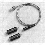
The CT1 and CT2 Current Probes are designed for permanent or semi-permanent in-circuit installation. Each probe consists of a current transformer and an interconnecting cable. The current transformers have a small hole through which a current carrying conductor is passed during circuit assembly.
High Sensitivity
The CT1 and CT6 provide an output of 5 mV for each milliamp of input current when terminated in 50 ©. The CT2 provides 1 mV per milliamp when terminated in 50 ©.
Typical Systems
The CT1, CT2 and CT6 high frequency current transformers are dynamic (i.e., non-DC) current measuring devices. They are typically used in conjunction with compatible high bandwidth oscilloscopes and other instruments to observe and/or record high frequency current waveforms. The CT1, CT2 and CT6 normally operate directly into 50 © scopes and other measuring device inputs.
The CT1 or CT2 can be used with 1 M© input systems; use the P6041 probe cable and terminate the output with a 50 © feed-through termination (see Optional Accessories).
In all cases, the CT1, CT2 and CT6 must work into 50 ©s to obtain specified performance and sensitivity.
Typical Measurement Applications
Differential Current Measurements
Most true-differential voltage amplifiers have a maximum bandwidth of about 100 MHz. The CT1 or CT6 can make differential current measurements to 1 GHz and 2 GHz, respectively, by passing two wires carrying opposing currents through the same core. The displayed result is the difference current. The CT2 can perform the same function to 200 MHz.
In all cases, Derating with Frequency and Amp-second Product (Current-time Product) guidelines should not be exceeded. (See Characteristics.)
Single-shot and Low Rep-rate Pulse Measurements
These common measurements are easy to make with the CT1, CT2 or CT6 provided that your signal fits within the Max Pulse Current and Amp-second Product (Current-time Product) guidelines for the specific current probe characteristics.
For example, the CT2 is rated at 36 Amps peak, with an Amp-Second Product of 50 x 10-6 Seconds (50 Amp-microseconds), therefore the CT2 can safely handle a 36 Amp peak pulse with a maximum width of 1.39 microseconds or lower amplitude pulses for longer pulse widths. The CT1, CT2 and CT6 all have low frequency rolloff characteristics. Low frequency "droop" will exhibit itself when the pulse width approaches the L/R time constant of the specific transformer.
Propagation Delay Measurements
Two CT1 or CT2 Current Transformers with matching probe cables can be used to measure propagation delay (transit time) between the input and output currents of high frequency devices. The probe outputs are connected to the inputs of dual channel real-time or sampling scopes.
Verification of any Probe/Cable/Scope System mismatch can be obtained by passing the same signal current through both probes and observing total system delay difference, if any.