Contact us for pricing and availability.
Description
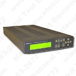
VM100 * VM101 Features And Benefits Automatically Measures 13 Key Video Parameters Differential Game Differential Phase Chrominance to Luminance Gain Chrominance to Luminance Phase Frequency Response 2T K-Factor Hum Signal to Noise Group Delay Bar Amplitude Sync Amplitude Burst Amplitude Luminance Non-linearity Verifies Compliance with Industry Standard TV Regulations Automatic "Signal ID" Fast, Accurate Measurements at a Touch of a Button Average Mode for Accurate Results in Low Signal to Noise Freeze Mode Suspends Testing to View Intermediate Results RS-232-C Port for Remote Access or Local Printer Output Simple and Intuitive Interface Internal Memory for Storage of Measurements Results Internal Time Clock for Dating Measurement Results RS-232-C Control Feature Allows Automatic Control of 1740A Series Waveform Monitor Line Select Mode for Viewing of Measured Signal Applications Low-cost Video Network Quality Monitoring FCC Compliance Monitoring for U.S. Cable TV Systems For quick verification and monitoring of the composite baseband video signal, the low cost VM100/101 is a perfect choice. Several key automatic video measurements may be selected with the results quickly and clearly displayed on a high-contrast LCD. Users with little experience in video testing will appreciate the VM100/101's compact size and intuitive push button interface. VM100 Automatic Video Measurements for FCC Compliance The VM100 makes standard NTSC video measurements including the baseband measurements required by new FCC cable system regulations. This makes the VM100 a good choice for CATV engineers charged with meeting those requirements. Measurements are initiated with the push of a button. Once completed, the measurement results may be viewed on the LCD, stored in an internal nonvolatile memory or copied to a serial printer for archival. An internal time clock automatically inserts the time and date of each test for later analysis. Measurement results are averaged for a stable reading even in the presence of a low signal-to-noise ratio. A freeze mode can be used to stop all measurement activity so that intermediate results may be examined. When the input signal lacks suitable synchronizing information, such as inverted sync used for video encryption, an external sync reference input can be used. VM101 Automatic PAL Video Measurements The VM101 is a low cost, fully automatic PAL video measurement set capable of recognizing 23 PAL test signals. Up to 13 industry standard measurements are constantly updated. Unlike other "automatic" low cost measurement sets, the VM101 requires no test configuration plan or PC setups to begin making measurements. Just apply a signal to the loopthrough input and the advanced test signal identification and analysis software does the rest. Measurements are completed quickly with absolutely no configuration required. Measurement results are viewed directly on the high contrast LCD, eliminating the need for an external display. Measurement results can also be monitored remotely via a simple modem connection, stored in an internal nonvolatile memory for later viewing or copied to a local serial printer for hardcopy documentation. All measurements are dated by an internal time clock, which provides an accurate time reference for all reports. Automatic signal averaging is calculated from the system signal-to-noise ratio, thus eliminating the subjective decision of how many times to average a measurement result. A special freeze mode can be used to stop all measurement activity so that intermediate results may be examined. When the input signal lacks suitable horizontal synchronizing information, an external sync reference input may be used. Automatic Test Signal Identification With the VM100/101 "Signal ID" feature, you no longer need to spend valuable time searching video for the correct test signal. The input signal is constantly scanned for all valid test signals. All test signals, as well as their field and line positions, are automatically identified for use with a selected measurement. Operators do not need to be trained to identify which test signal is used with a particular video measurement. RS-232-C Port for Remote Access or Printer Output A 9-Pin serial port is located on the rear panel of the VM100/101. This serial port can be used for copying measurement results directly to a local printer. In addition, a computer can be used to poll the VM100/101 from a remote location via a modem connection. A complete report can be retrieved and stored on a PC hard drive for documentation. A sample printout is shown in Figure 1. RS-2232 Controller Mode for Automatic Control of the Tektronix 1740A/1741A Waveform Monitor To further increase customer value as a measurement and analysis tool, the VM100/101 incorporates a unique RS-232 CONTROL mode feature. CONTROL mode allows a user to simultaneously view the test signal waveform that is currently being measured by the VM100/101 on a Tektronix 1740A/1741A waveform monitor. The VM100/101 automatically sends the appropriate RS-2332 commands (via the serial ports) to the waveform monitor in order to control the monitor display. An easy-to-use optional hardware kit is available that couples the VM100/101 directly beneath the 1740A/1741A waveform monitors. This compact, portable package is for measurement and trouble-shooting applications. Measurements Stored In Nonvolatile Memory Measurement results can be saved to internal nonvolatile "Channel Memories." This feature allows a user, proofing a multi-channel cable TV system, for example, to store individual measurement results as they progress through each channel. The VM100/101 can then be powered down, moved to another location and powered up again with the stored measurement results copied to a serial ASCII printer. All memory files include the original time and date of each test.
