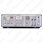
Tektronix TV1350
Television Demodulator
Contact us for pricing and availability.
Description
Features
Continuously Tunable Over All TV Bands and CATV Channels (HRC & IRC) to 880 MHz (Channels 2-99) with Synthesizer Precision for HRC and IRC
User-friendly Operation
Channel Selection by Digital Entry of Channel Number, Manual or Remote Modes, Plus Search
Automatic Compensation for Carrier Offsets to ±100 kHz
Switch Selectable Sound Trap
Switchable IF Gain for Improved S/N Ratio
Selectable Envelope or Synchronous Detection
Synchronous Detector Quadrature Output for Convenient Adjustment of Modulation Balance and ICPM Measurements
Stable Zero Carrier Reference for Video Level Adjustments and Residual Carrier Measurements
Available in Standards M, D/K, B/G, I and K1
Worldwide Audio Standards Available: Dual Sound, NICAM Prepared, Wideband Audio Out for BTSC Stereo Decoders
Built-in Loudspeaker, Headphone Jack and Deviation Meter
Parallel Remote Control Standard; IEEE-488 (GPIB) Bus Interface Optional
Applications
Off Air and Cable Measurements
The TV1350
The TV1350 family is capable of solving all problems in the field of TV reception and demodulation.
The Tektronix TV1350 Television Demodulator provides an accurate link between RF signals and baseband measuring equipment. It captures and demodulates TV signals with true fidelity and full transparency and is ideal for monitoring testing and adjustment applications in both TV transmitter and CATV systems.
Synthesizer frequency processing provides continuous coverage of all TV bands and cable channels. Channel selection is simply a matter of entering the channel number manually from the front panel or via the remote interface. A search mode facilitates automatic tuning. Accuracy is <2.5 kHz and carrier offsets to ±100 kHz are compensated automatically.
Up to 20 dB of built-in RF attenuation is selectable, either manually or automatically. The RF input level is indicated on an analog meter, with the optimal input level marked directly on the meter. Highly effective adjacent channel suppression is provided by a SAW filter.
The TV1350 offers user-selectable envelope or synchronous detection. Two isolated video outputs and two quadrature signal outputs facilitate convenient measurement of incidental phase modulation of the video carrier to determine the intercarrier S/N ratio of the sound channel. The quadrature signal output is especially suited for adjustment of linearity and phase equalizing circuits in TV transmitters. A stable zero carrier reference enables accurate measurement of the video modulation depth.
Frequency deviation of the sound carrier can be measured on the front panel analog meter. Narrow, wideband, mono and stereo BTSC audio outputs are available. Complex audio processing circuits maintain equal deviation of the two audio demodulators to ensure low stereo crosstalk. A built-in loudspeaker with a volume control and a headphone jack provide convenient monitoring of the audio signal. Parallel remote control capability is standard. An IEEE-488 (GPIB) bus interface is optional.
Key Features Common to the TV1350 Products Are:
Two isolated video outputs
Two quadrature outputs for ICPM measurements
Zero carrier reference pulse
Switchover from synchronous to envelope detection
Special Features
TV Test Receiver and Demodulator TV1350
Channel selection with digital entry of channel number either in manual or in remote mode
Automatic control of frequency offset up to ±100 kHz
Continuously tunable in all TV bands, also in special channels from 54 MHz to 880 MHz
SAW filter switch-selected on front panel for adjacent channel suppression
Optional GPIB control (IEC 625-1/IEEE 488), thus channel selection also possible by entering the vision carrier frequency
Reduction of IF gain allowing operation at high input levels (demodulator mode) and thus providing increased video S/N ratio
List of Options
| 01 | |
| 10 |